1.Introduction:
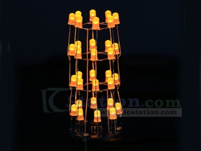
★It is an easy make four-layer round led dimensional cylinder kit. All are DIP components.
★It has more than 23 kinds of special led gradient effect. Some kinds of the effect is star-flashing and lightning effect.
★It also has many spin move effect and led breathing effect.
★All of the effects is gradual change light up instead of directly light up that makes the led animation looks more gentle.
★User can hang it up on the Christmas tree to simulate the star flashing effect.
★Soldering grids of each led layer by hand would look terrible, so it has a dual application round acrylic that can as a template to hold the led in place that help you to solder each layer of the led grids more accurate and the same level.
★It also use as a case to reinforce the bottom.This acrylic template is important for quality soldering and it makes the led cylinder easier and more precise.
2.Feature:
1>.28pcs highlight 5mm LED
2>.23 kinds display effects
3>.More than 10 random display modes
4>.Toggle Switch control flashing mode
3.Parameter:
1>.Work Voltage:DC 4.5V~5.5V
2>.Work Current:500mA
3>.Work Module:Switch Control
4>.Work Temperature:-40℃~85℃
5>.Work Humidity:0%~95%RH
6>.Size(Installed):44*44*108mm
4.Set Method:
1>.Switch button to change display mode.
5.Application:
1>.Training welding skills
2>.Student school
3>.DIY production
4>.Project Design
5>.Electronic competition
6>.Gift giving
7>.Crafts collection
8>.Home decoration
9>.Souvenir collection
10>.Graduation design
11>.Holiday gifts
6.Installation Tips:
1>.User needs to prepare the welding tool at first.
2>.Please be patient until the installation is complete.
3>.The package is DIY kit.It need finish install by user.
4>.The soldering iron can't touch the components for a long time(1.0 second), otherwise it will damage the components.
5>.Pay attention to the positive and negative of the components.
6>.Strictly prohibit short circuit.
7>.This DIY installation is more difficult to be installed, please be patient until the installation is complete!!!
8>.User must install the LED according to the specified rules.Otherwise some LED will not light.
9>.Install complex components preferentially.
10>.Make sure all components are in right direction and right place.
11>.Check that all of the LED can be illuminated.
12>.It is strongly recommended to read the installation manual before starting installation!!!
13>.The default code inside the chip, the function is more abundant,So please do not update the code inside arbitrarily!
7.Installation Steps(Please be patient install!!!):
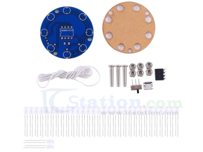
1>.Step 1: Install 3pcs Copper pillars and M3 Screw on Acrylic Welding Template.
2>.Step 2: Process 24pcs LED(Not all LED!!!).Curved LED’s shorter pin(negative pole) and form a right angle.Please be careful not to damage the LED.
3>.Step 3: Install the LED ring.Put the already processed LED on acrylic template.Longer pin(Positive pole) outward. Shorter pin(Negative pole) interconnection.
4>.Step 4: Use a soldering iron to fix LED the negative pole(Shorter pin).The soldering iron cannot touch the LED pins for a long time, otherwise it will damage the LED.
5>.Step 5: Cut off excess pins.Just cut shorter pin!!!
6>.Step 6: Install others 2pcs LED rings as the same method.
7>.Step 7: Install 1pcs MINI USB Female Socket at J1.
8>.Step 8: Install 1pcs Toggle Switch at S1.
9>.Step 9: Install 1pcs DIP-8 STC15F104W at U1.There is a dot on one corner of the IC and there is a mark on PCB where the IC can place on.These two marks are corresponding to each other and are used to specify the installation direction of the IC.
10>.Step 10: Install and fix the first layer LED ring.Note that the pins of these LED are not bent.
11>.Step 11: Put some tin on the root of positive pole in order to fix next layer LED.
12>.Step 12: Bend the next layer LED pins slightly in order to connect the 1st layer.
13>.Step 13: Connect LED layer.Please be patient when connecting each layer.
14>.Step 14:Connect the negative pole of the 2nd layer to COM2 by white wire. this layer of LED will flash normally if the power is turned on.
15>.Step 15: Install the 3rd layer of LED on the PCB and this layer connect to COM3 by white wire.
16>.Step 16: Install the 4th layer of LED on the PCB and this layer connect to COM4 by white wire.
17>.Step 17: Connect to power supply and enjoy the effect.


.jpg)

