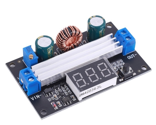
Battery Charger Discharger Board Undervoltage Overvoltage Charge Protection Board Charging Discharging Module
$4.75$6.7930%
| Quantity | 10+ | 30+ | 50+ | 100+ |
| Price | $4.69 | $4.55 | $4.40 | $4.20 |
00d : 00h : 00m : 00s
Item ID: 12325
Product Details
Description
Battery charge and discharge module integrated voltmeter, undervoltage and overvoltage protection timing charge and discharge with communication function.
Module Highlights:
1. Battery charge and discharge intelligent control;
2. You can set the charge and discharge time;
3. With serial communication function, real-time monitoring of the working status of the relay through the serial port;
4. Additional signal output, when the relay to meet the conditions, the output high, you can control other equipment.
5. A key emergency stop function (STOP button), with reverse protection, reverse does not burn.
Operating Mode:
Voltage upper limit: UL1, voltage lower limit nL1, the voltage upper limit is greater than the voltage lower limit (UL1> nL1)
U-1: Charging measurement:When the measured voltage is lower than the lower limit voltage, the relay pulls above; the upper limit voltage, the relay is disconnected.
U-2: charge measurement time control: set the charging time (OP); when the measured voltage is lower than the lower limit voltage, the relay pull, and then start the countdown OP time, the end of the timer, the relay off; when the measured voltage is higher than the upper limit voltage , The relay is disconnected.
U-3: Discharge detection: When the measured voltage is lower than the lower limit voltage, the relay is off, above the upper limit voltage, the relay pulls;
U-4: discharge detection time control: set the discharge time (OP); when the measured voltage is higher than the upper limit voltage, the relay pull, and then start the countdown OP time, the end of the timer, the relay off; when the measured voltage below the lower limit voltage , The relay is disconnected;
U-5: voltage in the range, the relay pull: when the measured voltage between the upper and lower limits, the relay pull, the other circumstances open;
U-6: voltage outside the interval, the relay pull: the measured voltage below the lower limit voltage or higher than the upper limit voltage, the relay pull, the other case the relay is off.
Product Parameters:
1: Power supply voltage: DC6--40V, voltage detection range DC 0--60V, suitable for less than 60V of the various batteries, voltage measurement error ± 0.1V.
2: charge and discharge time (OP) range: 0 - 999 minutes.
How do I set parameters?
1. First, according to their needs, to determine the requirements of the work model;
2. According to the working mode of the relay, in the main interface (when the module is powered on, it will flash the current mode of operation, the default U-1 mode, and then enter the main interface) press the SET button for 2 seconds and then release, enter the selection Mode interface, UP, DOWN button to select the mode to be set (U-1 ~ U-6);
3. After selecting the mode, assume that we have selected the U-1 mode and press the SET button to set the corresponding parameter. The parameter to be set will flash (UL1 voltage upper limit, nL1 voltage lower limit, OP conduction time), press UP, DOWN Key to increase or decrease, you can always press the key to quickly increase or decrease, press the SET button to set the current mode of the next parameter, the process above;
4. Set the parameters, and then press the SET button for 2 seconds to release, the current setting mode will flash, and then return to the main interface, set the parameters of success!
5. In the main interface, press the DOWN key to achieve voltage and time switching.
Mode selection interface: press the SET button for a long time to enter the mode selection interface, set the finished, a long time press the SET button and then release the exit mode selection interface, back to the main interface.
Additional Features:
1. Data upload: through the serial port to achieve data upload, interval 1s upload a voltage and run time, easy to post-data analysis;
2. Serial port settings parameters: You can set the mode and parameters through the serial port, more convenient;
3. An extra signal output, when the relay to meet the conditions, the output high, the other output low.
Serial port control (TTL level communication)
Communication standard:
The baud rate is 115200 bps
Data bits: 8
Stop bit: 1
Check digit: none
Flow control: none
Serial command:
"U-1": Operating mode (range U-1 to U-6)
"000": 0 - does not enable timing function, non-0 - enable timing function (range 001 to 999)
"Dw02.9": Set the lower limit voltage
"Up10.1": set the upper limit voltage (range 00.0V ~ 99.9V)
"Get": Get the current settings
"On": Allows the relay to turn on
"Off": Always turn off the relay
"Start": start uploading data
"Stop": stop uploading data
The above command can be any combination of two, need to be separated by commas
Such as: "dw02.9, up10.1" set the lower limit voltage 02.9V upper limit voltage 10.1V
Upload Status: Test Voltage + On Time + Status
"00.0V, 00: 00: 00, OP r n"
00.0V: Measured voltage
00:00:00: Relay on time
Status: OP relay on, CL relay off
STOP key function expansion:
Relay enable mode:
1. ON: OP conduction time, the relay allows conduction;
2. OFF: The relay is disabled and is always off;
Press the STOP button on the main interface to switch between ON and OFF, the current status will flash, and then return to the main interface. (This function is an emergency stop function, a key to disconnect the relay)
Sleep mode:
1. C-P sleep mode: within five minutes, without any operation, the digital tube automatically shut down the display, the program normal operation;
2. O-d normal mode: digital tube is always open display;
Press and hold the STOP button for 2 seconds to release, to achieve C-P and O-d state of the switch, the current state will flash, and then return to the main interface.
Pin Definition

Connection Way


Module Size

1. Tested by ICStation's Outstanding Partner adrirobot:
https://www.adrirobot.it/caricabatteria/modulo_controllo_batteria.htm
2. Tested by ICStation's Outstanding Partner Treicer100:


Learn More Details in the Video:
(The language in the video is Russian)
(The language in the video is Russian)


