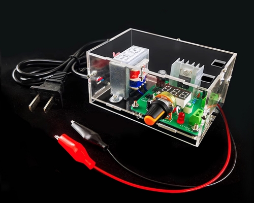
AC to DC Converter, Dual Output Step Down Power Supply Module, AC 85V-265V to DC +/-12V Buck Converter
| Quantity | 5+ | 10+ | 30+ |
| Price | $5.99 | $5.60 | $5.30 |
Product Details
Features:
1>. The product is easy to install and can be used in the hole welding line.
2>. There are fixed mounting holes in the corners to prevent the movement/vibration of the product without power, and the fixed hole is 3.2mm.
3>. Universal input voltage: 85-264V AC or 110-370V DC.
4>. High efficiency, low output ripple noise, double isolation output, high output voltage of main road (VO1).
5>. Input and output high isolation.
6>. With over-current protection, short circuit protection and temperature protection.
7>. The output is built in double - channel LC -π type filtering without external circuit.
Input Characteristic:
| No. | Input | Value |
| 1 | AC input(VAC) | 85-264 |
| 2 | DC input(VDC) | 110-370 |
| 3 | Frequency range(Hz) | 47-63 |
| 4 | Input current(A) | 1/115VAC 0.5/230VAC |
| 5 | Surge current(A) | Cold start:20A/230VAC |
| 6 | Workpiece ratio(TYP.) | 69 |
| 7 | Stand-by consumption(mA) | ≤1W/230VAC |
Output Characteristic:
| Input voltage(VDC) | ± 12V | |
| Input voltage precision | Main circuit: ±1%, Side circuit: ±10% | |
| Rated current(ADC) | 0.7A | |
| Rated power (W) | 17W | |
| Ripple and noise(mvp-p> | Rated input voltage, 20MHz band width | V01(V+)Mian circuit: 50mV |
| V02(V-) Side circiut: 100mV | ||
| Line Regulation | Full load | ±1% |
| Load Regulation | 10-100% load | ±3% |
| Start/up time | Full load |
2000ms, 30ms/l 15VAC 1000ms, 30ms/230VAC |
| Maintain (ms) | Full load |
16ms/l 15 VAC 50ms/230VAC |
| Overload protection | Rated input voltage | 115%^150% of rated output power |
| Protection mode: hiccup mode, the abnormal condition of abnormal load can be automatically returned. | ||
| Short-circuit protection | Rated input voltage | Long - term short circuit, self - recovery |
| Over-current protection | >1.1 time Io | |
| Start delay time(ms) | Vin:230 VAC | 500ms |
| Power-off protection time(ms) | 20ms | |
General Characteristic:
| Working temperature(℃) | / | -30 to 70 |
| Working humidity(RH) | / | 20 to 90%, non-condensing |
| Temperature drift coefficient | / | ±0.02%/℃ |
| Storage temperature and humidity | -40 to 85 Celsius 10-95%RH | |
| Switching frequency(KHz) | 20-65 | |
| Insulation voltage(VAC) |
Input to output Test 60s, ≤5 mA |
3000 |
| Insulation resistance (M Ohm) | Input to output500VDC | 100 |
| leakage current(mA) | 500VDC | Input to output ≤ImA/RMS Value |
| MTBF | @25 Celsius | 215000h |
| Safety class | / | Suitable for: CLASS B |
| Beam vibration | / | 10—500Hz 2G 10Minutes/cycle. X, Y, Z 60minutesrespectively |
| electromagnetic compatibility | / | Suitable for:EN55022(C1SPR22)Class B EN61000-3-2,-3 |
| Remark | 1. Except for special instructions, the parameters of this specification are measured at 230VAC, rated load and 25c ambient temperature. | |
| 2. Ripple and noise measurement method: use a 12 "twisted pair, and the terminal shall be connected in parallel with the capacitance of 0.1uf and 10uF, and shall be measured at 20MHz bandwidth. | ||
| 3. Accuracy: including the rounding error, linear adjustment rate and load adjustment rate. | ||
| 4. The power supply shall be regarded as part of the internal components of the system, which shall be confirmed by electromagnetic compatibility with the terminal equipment. | ||
| 5. The output should be reduced under low input voltage. | ||
Wiring Instruction:
1>. Typical circuit:

Output:
| Output voltage | C1/C3 | C2/C4 | TVS |
| 5V |
C1: 47uF/25V C3: 100uF/35V |
IUF/50V | SMBJ7.0A |
| 7V | SMBJI2.0A | ||
| 12V | SMBJ20.0A | ||
| 24V | SMBJ30A |
Remark:
C1: connection/coupling filter electrolytic capacitors.High frequency low resistance capacitance is recommended. The noise from the connector can be removed when the capacitance pressure drop is greater than 75%.
C2: ceramic capacitors to remove high frequency noise.
TVS: protection of the back - level circuit when the power supply is abnormal. Recommended.
C1, C2, C3, C4: the product with no requirement for power output ripple is not used.
2>. Emergency solution--Recommended circuit:

Input:
| Component No./ Recommended component | Function | Recommended value |
| CX1 capacitance | Restrain the interference of common mode, improve the anti-jamming ability and reliability of the system. | 0.22uF/275VAC |
| R1/R2: leakage resistance. | 1M ohm 1/2W | |
| NF: common mode inductance. | 10 mH-30 mH |
Pin Definition:


