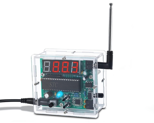
PLL LCD Digital FM Stereo Radio Receiver Module 50Hz-18KHz Wireless Microphone Module DC 3-5V with LCD Display
$9.09$12.9930%
| Quantity | 3+ | 5+ | 10+ |
| Price | $9.05 | $8.85 | $8.50 |
00d : 00h : 00m : 00s
Item ID: 10545
Product Details
Description:
This digital FM stereo radio circuit board module has built-in DSP digital noise processing. When there is no signal, it will automatically mute and get rid of the noise of traditional FM radio.
This digital FM stereo radio circuit board module has built-in DSP digital noise processing. When there is no signal, it will automatically mute and get rid of the noise of traditional FM radio.
Product Introduction:
1>. Output Power:500mW (driving earphone);3Wx2 (driving loudspeaker)
2>. Frequency Response Range:50Hz-18KHz
3>. Receiving Frequency Range:87.0MHz-108.0MHz (campus broadcast power off);76.0MHz-108.0MHz (campus broadcast power on)
4>. Equivalent Noise:>=30dB
5>. Power Supply Voltage:3.0V-5.0V
6>. Power Supply Current:1000mA (max volume);60mA (minimum volume)
7>. Sound Track:stereo
Features:
1>. Adopt DSP And FM PLL Technique
2>. LCD Display
3>. 30 Levels Digital Volume Adjustment
4>. Power Off Automatic Memory Previous Data
5>. Loudspeaker/Earphone Output Automatic Shift
6>. Adopt Quartz Crystal Stabilizing Frequency
7>. Adopt Audio DSP To Analyse Audio Signal
8>. Adopt Incremental Digital Rotary Encoder To Adjust Volume And Frequency
9>. 30 Levels Digital Volume Adjustment Range
10>. Support Serial Port Communication Control
Note:
1.The supply voltage is strictly prohibited to exceed the supply voltage range of this module.
2. Do not touch the rear of the module when working, so as not to affect the normal work of this module or cause the short-circuit module to burn out.
1.The supply voltage is strictly prohibited to exceed the supply voltage range of this module.
2. Do not touch the rear of the module when working, so as not to affect the normal work of this module or cause the short-circuit module to burn out.
Instruction:
1>. Power supply
Corresponding door module (marked on the PCB).
"-" E "+" are the anode and the supply cathode (battery). The power supply is recommended for the battery or other stabilized power supply. It is not possible to use a power supply without filter (for example as a mobile phone charger, mobile power supply, and other switching power supply), otherwise, the interference caused by power supply will affect the normal work of this module. The normal operating voltage of this module is 3.0-5.0 V, not exceeding this range. At maximum module volume, the maximum power supply current is around 1A, which requires the battery for enough output current.
2>. Antenna
The FM_ANT port is used to connect the FM antenna. To better receive the FM signal, it is recommended to extend the antenna with a length of 75 centimeters.
3>. Headphone / speaker output
This module is with 3WX2 channel audio amplifier. If the horn is needed, access the speaker port. We recommend using 4 Ω / 3 w speakers. if the headset is plugged in, the audio will automatically switch to the channel headphone, and the channel speaker will be closed automatically.
4>. Volume
Turn the VOL encoder to adjust the volume, while the LCD display shows the volume of the series.
5>. Frequency regulation
Turn the FRE to adjust the reception frequency, while the LCD display shows the current frequency, and press the encoder handle for the mute / non-mute switch.
6>. Mute
Press the VOL knob to switch the mute / non-mute button down.
7>. AMCAP switch
Long press the FRE knob to turn on or off the AMCAP, the LCD subtitle display ON means to turn on the AMCAP, and means to turn off the AMCAP.
8>. AMCAP threshold adjustment (when the AMCAP switch is on)
Briefly press the FRE knob for AMCAP interface threshold adjustment, it is possible to adjust the threshold movement of the AMCAP according to the specific use situation. The adjustment range is 0-20. The higher the value is, the higher the threshold is, the easier the weak signal is to be silent. The other way around.
9>. Serial port (without serial port control)
The reserved interface control module of the serial port at TTL level. TTL serial port and this communication module need to connect the module of the UART_RX, UART_TX and GND (the corresponding position of PCB is marked). You can use the external MCU or the serial port of the computer to send the module control command related functions. Note: because the serial port of the computer is not at TTL level, connect the communication computer, it is necessary to connect the RS323 level TTL power leveling device or the USB CABLE serial port at TTL level to communicate with this module. This operation requires professionals.
10>. User settings
This module can set the backlight state according to user specific usage. When the power is off, press the FRE button to turn on, and the B0 indicates that the backlight is always bright. B0 indicates that the backlight is closed for 20 seconds, and the setting is effective after restarting. Change the Status Settings to repeat this step to move on. The backlight has no operation for 20 seconds.
11>. Stereo / mono terminal switch.
Stereo / mono terminals are used to set the reception mode of the FM module. This terminal is suspended for Stereo reception mode, and it is a single channel reception mode.
FM with squelch AT receiver module instruction set:
Transmission speed: 38400 TTL level

Connection Picture:
(This module has a slight difference now. The current version is No Wires beside the LCD. Thanks for your attention.)
(This module has a slight difference now. The current version is No Wires beside the LCD. Thanks for your attention.)


Effect Picture:

I. Tested by ICStation's Outstanding Partner 12voltvids:


Learn More Details in the Video:
(The language in the video is English)
(The language in the video is English)
II. Tested by ICStation's Outstanding Partner wonders of science:


Learn More Details in the Video:
(The language in the video is English)
Customer Reviews (1)
You Might Also Like
-
 32GB Memory Card
$3.91$5.59


