
- prev
- next
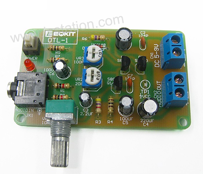
DIY Module OTL Power Amplifier Circuit DIY Kit OTL Discrete Component Amplifier Electronic Production Suite
Product Details
Description:
This is a DIY OTL Power Amplifier Kit parts. You should solder it by yourself. This circuit belongs to the OTL circuit teaching model, its maximum power is only 1W, driven by two complementary transistors S8550 and S8050.It can be used for exercise welding techniques, understanding the triode complementary OTL output type and how to adjust the static operating point, midpoint voltage, etc..
Features:
1>.High sensitivity;
2>.Low power;
3>.Wide operating voltage range;
4>.Low power consumption;
5>.DIY design;
Parameters:
| No. | Parameter | Value |
| 1 | Model | OTL-1 |
| 2 | Standby current | Less than 5mA |
| 3 | Soldering difficulty Level | Easy |
| 4 | Working voltage | DC 4V-9V(Recommend 5V) |
| 5 | Working current | Less than 100mA |
| 6 | Output power | 1W(max) |
| 7 | Output Type | Single power supply OTL |
| 8 | PCB Size | 65*40mm |
Working principle:
1>.This circuit belongs to the OTL circuit teaching model, its maximum power is only 1W, driven by two complementary transistors S8550 and S8050;
2>.The working voltage of this kit is DC4-9V, the recommended voltage is 5V.
Instructions:
Step 1: Complete the installation in the normal way following installation manual and schematic.(Please request separately).
Step 2:Connect DC 4-9V voltage;
Step 3:Adjust potentiometers.
Step 4:Test and use.
Adjust Static Working Point:
1>.Turn VR1,VR2,VR3 counter clockwise to the end.Turn on power supply,The red cable of the multimeter connect TP1,Black cable of multimeter connect to GND.Adjust potentiometer VR2 to make sure the voltage is half of the power supply at TP1.(For example:The power supply voltage is 8V,So the voltage ofthe TP1 should be adjusted to 4V by VR2).
2>.Connect the ammeter to the power supply circuit,Then you will get the static current of the circuit.At this time,please adjust potentiometer VR3 to increase the current value of the circuit to 0.5mA.
When you input the audio signal at this time, you can have sound output(It need connect speaker by yourself).
3>.Optimum working voltage DC4-9V,Maximum output power is 1 watts!
Using Attention:
1>.Please make sure all components in right direction and right place.
2>.Please check whether pseudo/float welding.This is very important .
3>.The soldering iron can't touch the components for a long time, otherwise the components will be damaged because of the high temperature.
4>.It is recommended to use a stable power supply, otherwise it may interfere with the audio signal output.
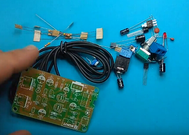
Component list:
| NO. | Component Name | PCB Marker | Parameter | Quantity |
| 1 | Metal Film Resistor | R4-R5 | 100ohm | 2 |
| 2 | Metal Film Resistor | R6 | 470ohm | 1 |
| 3 | Metal Film Resistor | R1-R2 | 1K | 2 |
| 4 | Metal Film Resistor | R3 | 4.7K | 1 |
| 5 | Metal Film Resistor | R7 | 10K | 1 |
| 6 | Ceramic Capacitor | C7 | 101P 100pF | 1 |
| 7 | Ceramic Capacitor | C2 | 104P 0.1uF | 1 |
| 8 | Electrolytic Capacitor | C3 | 2.2uF | 1 |
| 9 | Electrolytic Capacitor | C5-C6 | 100uF | 2 |
| 10 | Electrolytic Capacitor | C1,C4 | 220uF | 2 |
| 11 | Diode | D1 | 1N4148 | 1 |
| 12 | Red LED | LED1 | 3mm | 1 |
| 13 | Transitor S8050 | Q1,Q2 | TO-92 | 2 |
| 14 | Transitor S8550 | Q3 | TO-92 | 1 |
| 15 | Potentiometer | VR3 | 100ohm | 1 |
| 16 | Potentiometer | VR2 | 20K | 1 |
| 17 | Potentiometer | VR1 | 10K | 1 |
| 18 | Switch | SW1 | 6*6mm | 1 |
| 19 | Terminal KF301-2P | CN1-CN2 | 3.08mm | 2 |
| 20 | Audio Socket | JK1 | 5Pins | 1 |
| 21 | Audio Cable | JK1 | 1 Meter | 1 |
| 22 | PCB | OTL-1 | 65*40mm | 1 |
Note: You can finish installation by PCB silk screen and component listing.
Application:
1>.Electronic teaching
2>.Exercise welding skills
3>.Circuit application
Frequency asked questions:
1>.Why can't work?
Q :Please make sure all components in right direction and right place and check whether pseudo/float welding.This is very important.
Install tools you need preliminary preparation by yourself:
1>. Soldering iron;
2>. Multimeter;
3>. Solder wire;
4>. Iron stand;
5>. Diagonal cutting pliers;
6>. The screwdriver;
7>. Tweezers;
8>. Long nose pliers;
9>. Suction tin;
10>. Cleaning sponge;
11>. Screwdriver set.
Download installation manual and schematic:
.png)
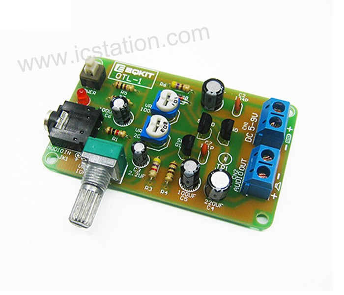
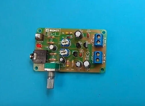
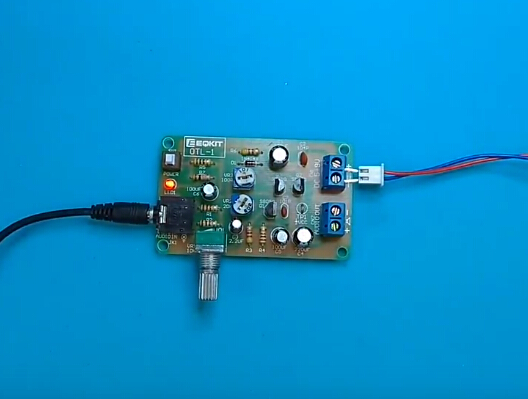
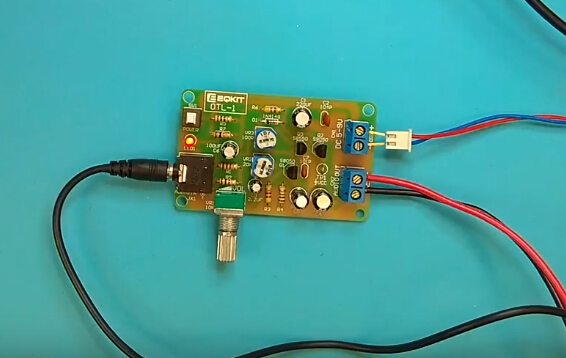
Finished Product Picture:
.JPG)
Tested by ICStation's Outstanding Partner bzoli5706:
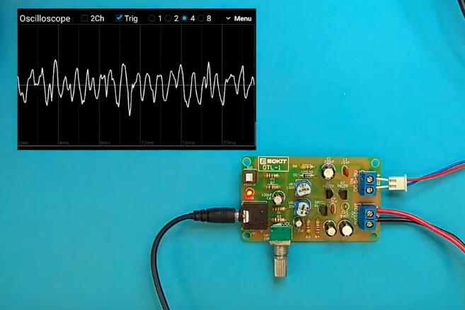
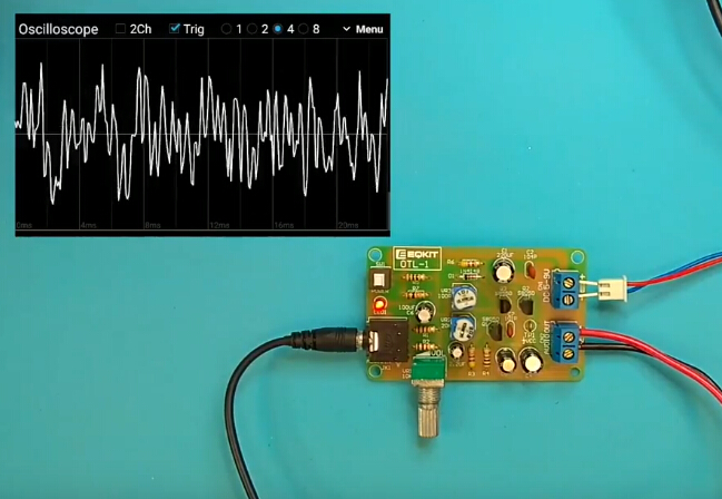
Learn More Details in the Video:
(The language in the video is English)


