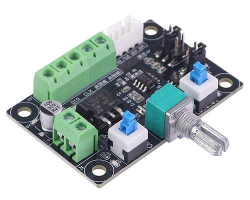
DC Motor Driver Board Module PWM Speed Controller DC 6V 12V 24V 36V 15A Regulator Module DC 6-36V
Product Details
12/24 / 36V 15A high-power DC motor drive plate module industrial positive and negative can be full PWM speed
Product Description:
Industrial design, stable and reliable, with anti-static circuit, transient suppression protection, undervoltage protection, interface ESD and over-voltage protection;
PWM effective range of 0.1% to 100.0%; for single-chip and other controllers to provide 5V power supply.
15A high-power DC motor drive board, stable and reliable, industrial grade
Product Type:
XY-15AS


Product Highlights:
1. Product industrial design, stable and reliable, with anti-static circuit, transient suppression protection, undervoltage protection, interface ESD and over-voltage protection;
2. Support voltage 9-36V wide range, the maximum sustained load current 12A (without heat), 15A (simple heat), 20A (thick large radiator);
3. similar to L298 drive logic, three lines (PWM, IN1, IN2) control speed, forward and reverse and brake;
4. Support full PWM, can be directly used to control the positive and negative keys, PWM effective range of 0.1% to 100.0%;
5. For the microcontroller and other controllers to provide 5V power supply, and 5V output overcurrent protection, and access signal overvoltage protection.
Control Signal Logic:
Note: 0 is low, 1 is high, × is any level, floating is low.
COM for the signal ground, 5VO 5V output, for the microcontroller and other controllers to provide 5V power supply;
PWM pin external PWM, if the use of key control, PWM pin should be connected with the 5VO;
IN1 and IN2 for the two motor positive and negative turn, brake control signal.
| IN1 | IN2 | PWM | OUT1、OUT2 Output |
| 0 | 0 | × | brake |
| 1 | 1 | × | float |
| 1 | 0 | 1 | Full speed |
| 0 | 1 | 1 | Full speed reversal |
| 1 | 0 | PWM | Forward speed |
| 0 | 1 | PWM | Return speed |
Product Parameters:
1. Power supply voltage 6V-36V (voltage is too low, large load current easily lead to damage to the module, so the circuit board labeled 9-36V),
the power must not be reversed or more than 37V, or may burn the module, it is recommended that the power Input in series 20A fuse.
2. Drives without heat sink rated current 12A, rated current 12A ~ 15A need to do simple cooling, 15A ~ 20A need to do thick heat sink.
(simple cooling - such as in the module below a 1mm thick thermal insulation silicone pad, and then 5mm copper column to the module fixed to the wall)
3. Control signal interface (orange) can provide users with external 5V, microcontroller no additional power supply, the maximum supply current 0.5A.
4. Control signal high voltage: 2.0V ~ 5.5V, compatible with 3.3V and 5V TTL level;
Control signal low voltage: 0V ~ 0.8V, 0V when floating;
When the control signal voltage is 5V, the control signal current is 50uA.
5. PWM effective range: 0.1% ~ 100.0%;
PWM signal frequency range: 0 ~ 100KHz (recommended 20KHz);
PWM minimum effective pulse width: 200ns.
6. Operating temperature -25 ℃ -80 ℃.
7. Product Size: 55 * 55 * 25mm (length and width).
8. Mounting hole diameter: 3mm.
9. Weight: 38g.


Suitable for Motor Parameters:
(Please do your own according to the motor parameters to do a simple cooling or thick heat treatment)
1. Rated voltage of 36V motor
The rated power of 300W and below or rated the rated current of 12A the following motor for a long time to work without cooling;
Logo rated power 300W ~ 370W or rated current 12A ~ 15A motor need to do a simple heat treatment;
Rated rated power 370W ~ 500W or rated rated current 15A ~ 20A motor need to do thick heat treatment;
2. Rated voltage of 24V motor
Marking the rated power of 200W and below or mark the rated current of 12A the following motor for a long time to work without cooling;
Logo rated power 200W ~ 250W or rated rated current 12A ~ 15A motor need to do a simple heat treatment;
Rated rated power 250W ~ 330W or rated rated current 15A ~ 20A motor need to do thick large heat treatment;
3. Rated voltage of 12V motor
Marking the rated power of 70W and below or mark the rated current of 12A the following long motor full work without heat;
Logo rated power 70W ~ 90W or rated current 12A ~ 15A motor need to do a simple heat treatment;
Logo rated power 90W ~ 120W or rated rated current 15A ~ 20A motor need to do thick heat treatment;
(This drive is not cooling under the conditions of rated current 12A, rated current 12A ~ 15A need to do simple cooling,
15A ~ 20A need to do thick heat. Motor rated power is generally refers to the output power, consider the motor work loss,
so the calculation Rated current to be considered motor efficiency, rated current = rated power / rated voltage / efficiency)
How to use it:
1. Use the microcontroller to control the motor rotation wiring method
Single-chip power supply to connect the drive module COM; PWM pin to the microcontroller's PWM output, for speed, or directly connected to the high-level full speed operation;
IN1, IN2 and the microcontroller's two IO connected to control the motor is reversing and Brakes;
5VO can provide 5V power supply for the microcontroller.
.png)
2. Use only the keys to control the motor reversing the wiring method
PB1 and PB2 are two keys. When the PB1 is pressed and PB2 is not pressed, IN1 is high, IN2 is low, the motor is turning;
when PB2 is pressed and PB1 is not pressed, IN1 is low, IN2 is high, Motor reverse;
when PB1 and PB2 are bounced, IN1 and IN2 are low, the motor brake.

3. Use OUR PWM generator to the motor speed control wiring method
PWM generator can be set by the key, select the frequency and duty cycle to control the motor speed;
PB1 and PB2 for the two buttons were to control the direction of rotation of the motor, when PB1 and PB2 are bounced, the motor is braking.

Precautions:
1. The drive supply voltage should be between 6-36V. If the power exceeds the rated voltage, it may burn the drive; the voltage is too low, the load current is large, may also cause the drive to burn.
It is recommended to connect the 20A fuse in series at the power supply.
2. In the forward and reverse switching time is best to brake more than 0.1S and then reverse, otherwise it may damage the drive.
3. Since the control signal line is very fragile, any signal lines (orange terminals) of the control signal can not be routed together with the wiring of the power supply or motor during use.
Otherwise, the drive may be burned and difficult to be repaired.
4. When the drive is powered down, do not turn the motor quickly, or the motor's electromotive force may burn the drive.
If the application requires the drive to power down when the machine should also quickly turn the motor, it is recommended in the drive motor interface string of a relay, relay coil and drive power supply.
In this way, when the power supply is turned off, the relay disconnects the drive from the motor.
5. The drive should be connected to the motor before it is powered on, otherwise it may burn the fuse or drive.
6. Motor interface must not be short-circuited, otherwise it may burn the fuse or drive.
7. Note that the drive does not get wet, do not let the components on the drive board short circuit, do not touch the components on the board pins and pads.
8. Please carefully read the product before use, if your error caused the module damage, or you have unauthorized replacement of the module device, no refund.


